💡 Getting started
Assembly
Due to the high amount of components integrated in such small PCB layout, most of them are too small to be soldered at home by you. Therefore, these boards come already with the components assembled.
The Smart Plant, in addition to the PCB assembled board, consist on the following parts:
A 2.9” e-paper display. The recommend (and tested working) e-ink panel is the 296x128, 2.9inch E-Ink raw display panel that you can order directly on the manufacturer. Please note that other displays may not work at all.
A LiPo battery, with a recommended 1000mAh capacity, for space and power. The ideal dimensions shouldn’t excess the 50x34x5mm in order to fit in the designed enclosure.
An enclosure where to fit the Smart Plant upper part that you can find on the enclosure section.
Optionally, you can mount a solar panel that charges the battery under the right sunny conditions. The output voltage of the panel musn’t excess the 6V and the recommended size to fit in the designed enclosure is 80x45mm
Powering
The Smart Plant is be powered through a LiPo battery plugged into the white JST connector. The voltage of the battery is regulated to the working 3.3V through a low-consumption LDO.
Caution
Connect the battery after clamping the e-paper connector and be careful when plugging it or removing it, since the connector can collide with some SMD components.
In order to charge the battery, there is a battery management IC that provides the right charging curve to the LiPo battery and offers a visual indicator (red LED for charging, green LED for standby) while the battery is being charged. There are two ways of charging the Smart Plant: USB-C or solar panel.

Solar panel

In addition to the USB-C, and with the aim of extending the service time between (USB) charges of the battery, the Smart Plant can be configured to be powered from a solar panel. This version is not the default one, and would imply soldering the solar pannel to the board as indicated in the figure.
USB-C
The USB Type-C is a very extended port for portable electronics, and because of it’s standarized 5V power supply is ideal for charging the Smart Plant since the battery management IC is designed to charge a 1000mAh.
Sensors
As the Smart Plant is intended to work during long periods of time without having to be recharged, it is important to avoid undesired consumptions durint the deep-sleep periods. This implies that the sensors have to be powered only when they are needed.
Therefore there is a high-switch circuit that enables/disables the powering of the sensors power line connected to the microcontroller’s output GPIO16.
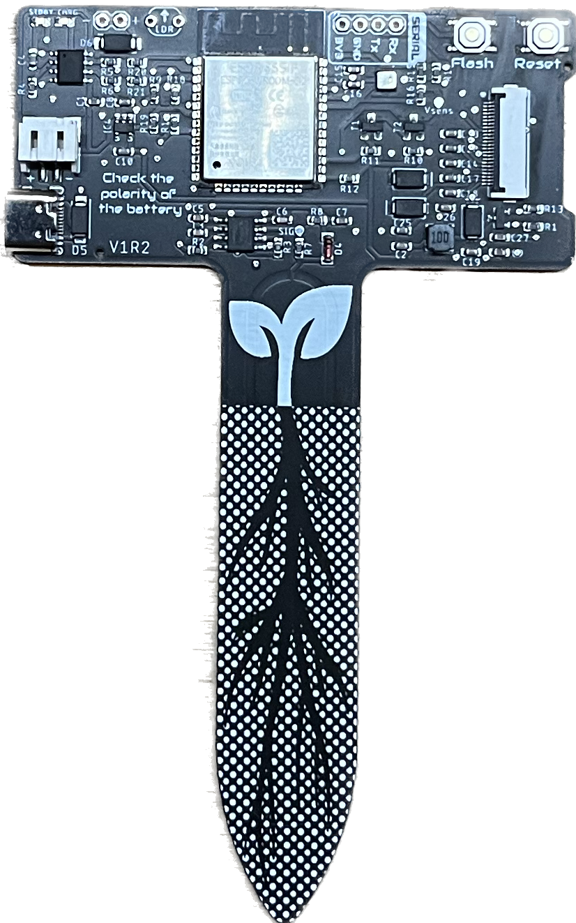
Soil moisture

Since the Smart Plant can be directly inserted into the soil of your pot, the area inserted contains a printed circuit that behaves as a probe that measures the soil capacity, determined by the soil moisture. As it has no metallic electrodes, there is no risk of probe degradation with time.
The moisture level, in a 0-3.3V range, is measured through the ADC on GPIO32
Light sensor
The illuminance is measured through the ADC on GPIO33, and while it’s still under test which illuminance transducer to use, the internal circuit can accept LDR or photodiodes.
Hint
If you are designing your own enclosure, make sure there is a hole for the light sensor on the case.
Ambient temperature & humidity

The Smart Plant embeds an AHT20 temperature and humidity sensor ready to deliver calibrated data through the IIC (\(I^2C\)) bus:
- SDA
GPIO21
- SCL
GPIO22
Battery level
This version (V1R1) is not capable to measure the voltage of the battery, and therefore the battery level.
E-paper
The e-ink display pinout with respect to the ESP32 GPIOs goes as follows:

ESP32 |
E-paper |
|---|---|
25 |
BUSY |
26 |
RST |
27 |
DC |
13 |
CLK |
14 |
MOSI |
15 |
CS |
Enclosure
The Smart Plant PCB can be mounted in a custom enclosure that you can print on your own 3D printer.