💡 Details
Pinout
The Smart Plant integrates an ESP32-S2 microcontroller with the following pinout:
Component |
Pin |
Description |
|---|---|---|
I²C |
||
Serial Clock Line (SCL) |
GPIO34 |
Used for I²C communication clock signal |
Serial Data Line (SDA) |
GPIO33 |
Used for I²C communication data signal |
SPI |
||
Clock (CLK) |
GPIO12 |
SPI clock signal |
Master Out Slave In (MOSI) |
GPIO11 |
SPI data from master to slave |
Analog/Digital Sensors |
||
Battery Voltage (ADC) |
GPIO2 |
Reads battery voltage level |
Solar Input (ADC) |
GPIO3 |
Reads voltage from the solar input pad |
Soil Moisture (ADC) |
GPIO1 |
Measures soil moisture |
Digital Outputs |
||
Excitation Switch |
GPIO4 |
Controls excitation signal for powering the sensors |
Display (WaveShare E-Paper) |
||
Chip Select (CS) |
GPIO10 |
Selects the e-paper display module |
Data/Command (DC) |
GPIO13 |
Differentiates between data and commands |
Busy Indicator (BUSY) |
GPIO14 |
Signals when the display is busy |
Reset (RST) |
GPIO15 |
Resets the display module |
Power
The Smart Plant is be powered through a LiPo battery plugged into the white JST connector. The voltage of the battery is regulated to the working 3.3V through a low-consumption LDO.
Caution
Connect the battery after clamping the e-paper connector and be careful when plugging it or removing it, since the connector can be hard to plug/unplug.
In order to charge the battery, there is a battery management IC that provides the right charging curve to the LiPo battery and offers a visual indicator (red LED for charging, green LED for standby) while the battery is being charged. There are two ways of charging the Smart Plant: USB-C or solar panel.

Solar panel

In addition to the USB-C, and with the aim of extending the service time between (USB) charges of the battery, the Smart Plant can be configured to be powered from a solar panel. This feature would imply soldering the solar pannel to the board as indicated in the figure.
USB-C
The USB Type-C is a very extended port for portable electronics, and because of it’s standarized 5V power supply is ideal for charging the Smart Plant.
Sensors
As the Smart Plant is intended to work during long periods of time without having to be recharged, it is important to avoid undesired consumptions durint the deep-sleep periods. This implies that the sensors have to be powered only when they are needed.
Therefore there is a high-switch circuit that enables/disables the powering of the sensors power line connected to the microcontroller’s output GPIO4.
Regarding the sensors, and except for the soil moisture sensor which is analog, the rest (illuminance, temperature & humidity, battery status) are IIC (\(I^2C\)) sensors, which are physically defined with the following pinout:
- SDA
GPIO33
- SCL
GPIO34
Soil moisture

Since the Smart Plant can be directly inserted into the soil of your pot, the area inserted contains a printed circuit that behaves as a probe that measures the soil capacity, determined by the soil moisture. As it has no metallic electrodes, there is no risk of probe degradation with time.
The moisture level, in a 0-3.3V range, is measured through the ADC on GPIO1
Light sensor
The illuminance is measured through a digital sensor VEML7700-TR. This sensor is located facing the outside of the top part of the board, so it would be facing the sky.
The VEML7700 is quite a convenient sensor since it delivers the values directly in lux. The sensor has 16-bit dynamic range for ambient light detection from 0 lux to about 120k lux with resolution down to 0.0036 lx/ct, with software-adjustable gain and integration times.
The \(I^2C\) address is 0x10.
Hint
If you are designing your own enclosure, make sure there is a hole for the light sensor on the case.
Ambient temperature & humidity
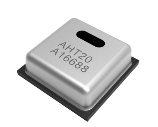
The Smart Plant embeds an AHT20 temperature and humidity sensor ready to deliver calibrated data through the \(I^2C\) bus.
This sensor has an operational relative humidity range of 0 to 100% ( with a ±3 % typical accuracy), and a temperature range of -40 to 85 °C (±1 °C typical accuracy)
The \(I^2C\) address is 0x38.
Battery level
For measuring the battery level, the Smart Plant integrates the MAX17048 IC.
This sensor measures the voltage of the LiPo cell and does the math to get an estimative percentage of the battery level.
The \(I^2C\) address is 0x36.
E-paper
The e-ink display pinout with respect to the ESP32 GPIOs goes as follows:

ESP32 |
E-paper |
|---|---|
14 |
BUSY |
15 |
RST |
13 |
DC/MISO |
12 |
CLK |
11 |
MOSI |
10 |
CS |
Enclosure
The Smart Plant PCB can be mounted in a custom 3D printable enclosure that you can print on your own 3D printer.
